TASCAM Ministudio Porta 03 MKII / Porta 03
Owner's Manual
TASCAM — TEAC Professional Division
This owner's manual covers both the PORTA 03 MKII and PORTA 03.
Copyright 1990, TEAC Corporation. Document Number: 9101404300
Safety Instructions
CAUTION: Read all of these instructions. Save these instructions for later use. Follow all warnings and instructions marked on the audio equipment.
- Read Instructions — All the safety and operating instructions should be read before the appliance is operated.
- Retain Instructions — The safety and operating instructions should be retained for future reference.
- Heed Warnings — All warnings on the appliance and in the operating instructions should be adhered to.
- Follow Instructions — All operating and use instructions should be followed.
- Water and Moisture — The appliance should not be used near water — for example, near a bathtub, washbowl, kitchen sink, laundry tub, in a wet basement, or near a swimming pool, etc.
- Carts and Stands — The appliance should be used only with a cart or stand that is recommended by the manufacturer. An appliance and cart combination should be moved with care. Quick stops, excessive force, and uneven surfaces may cause the appliance and cart combination to overturn.
- Wall or Ceiling Mounting — The appliance should be mounted to a wall or ceiling only as recommended by the manufacturer.
- Ventilation — The appliance should be situated so that its location or position does not interfere with its proper ventilation. For example, the appliance should not be situated on a bed, sofa, rug, or similar surface that may block the ventilation openings, or placed in a built-in installation, such as a bookcase or cabinet that may impede the flow of air through the ventilation openings.
- Heat — The appliance should be situated away from heat sources such as radiators, heat registers, stoves, or other appliances (including amplifiers) that produce heat.
- Power Sources — The appliance should be connected to a power supply only of the type described in the operating instructions or as marked on the appliance.
- Grounding or Polarization — The precautions that should be taken so that the grounding or polarization means of an appliance is not defeated.
- Power-Cord Protection — Power-supply cords should be routed so that they are not likely to be walked on or pinched by items placed upon or against them, paying particular attention to cords at plugs, convenience receptacles, and the point where they exit from the appliance.
- Cleaning — The appliance should be cleaned only as recommended by the manufacturer.
- Power Lines — An outdoor antenna should be located away from power lines.
- Outdoor Antenna Grounding — If an outside antenna is connected to the receiver, be sure the antenna system is grounded so as to provide some protection against voltage surges and built up static charges.
- Nonuse Periods — The power cord of the appliance should be unplugged from the outlet when left unused for a long period of time.
- Object and Liquid Entry — Care should be taken so that objects do not fall and liquids are not spilled into the enclosure through openings.
- Damage Requiring Service — The appliance should be serviced by qualified service personnel when:
- The power-supply cord or the plug has been damaged; or
- Objects have fallen, or liquid has been spilled into the appliance; or
- The appliance has been exposed to rain; or
- The appliance does not appear to operate normally or exhibits a marked change in performance; or
- The appliance has been dropped, or the enclosure damaged.
- Servicing — The user should not attempt to service the appliance beyond that described in the operating instructions. All other servicing should be referred to qualified service personnel.
WARNING: TO PREVENT FIRE OR SHOCK HAZARD, DO NOT EXPOSE THIS APPLIANCE TO RAIN OR MOISTURE.
CAUTION: TO REDUCE THE RISK OF ELECTRIC SHOCK, DO NOT REMOVE COVER (OR BACK). NO USER-SERVICEABLE PARTS INSIDE. REFER SERVICING TO QUALIFIED SERVICE PERSONNEL.
The Ministudio Porta 03 Is...
The MINISTUDIO PORTA 03 is a handy audio production facility in a single, compact box. It contains a four-track, four-channel cassette recorder with Dolby B noise reduction system and a basic mixer with two input channels. The four tracks can be mixed together to a stereo output or headphones using the built-in 4x2 tape cue mixer.
The PORTA 03 recorder uses conventional cassette tapes and records and plays at a standard speed of 1-7/8 inch per second (4.8 cm/sec.), providing the capability of playing tapes recorded on stereo cassette recorders as well (see "Track Format" in the section "Precautions and Recommendations").
Using the Manual
Understanding what is going on inside your equipment will help improve your sound. Think of this manual as a reference handbook. You won't need all of what is here in every situation, and certainly not necessary to memorize it, but try to find the time to read it thoroughly at least once, that way you will be familiar with its contents and if you need answers, they will be here waiting.
Use of Capital Letters
In general, we all use upper case type to designate a particular switch, control, jack name or label (like PAN). Transport modes and some features are described with an upper case first letter (like Record mode).
Precautions and Recommendations
1. Track Format
The PORTA 03 needs the entire width of the tape to record its four tracks, eliminating the option of recording on both sides. Therefore, you should decide which side cassettes are "A" or "B", you want to use and use that side exclusively. It's a good idea to get into the habit of consistently use the same side on all multitrack tapes.
Tracks 1 and 2 of the PORTA 03 are compatible with standard (Philips) stereo cassette tapes. The PORTA 03 can play back standard cassette tapes (when TRK 3 and 4 level controls are off, and recordings made on Track 1 and 2 of the PORTA 03 can be played back in standard consumer cassette decks. Note, however, that recordings onto Track 3 and 4 will not play back on a standard deck. Four-track recordings must be mixed down onto a standard stereo deck for distribution.
2. Tape Type
The PORTA 03 is internally adjusted for HIGH BIAS Type II tape. For best results, you should only use tapes of this type. TDK SA, Maxell XL-II or equivalent formulations are recommended. We strongly suggest that you select one good quality brand and use it exclusively. The time you'd spend creating your multitrack master is much more valuable than the money you save by buying inferior tape. The cassette shell eventually becomes a part of the PORTA 03's transport. Poor quality shells can cause wrinkles, snarls and shredding of the edges of the tape with use. Even small scratches on the tape oxide can cause "dropouts" (momentary loss of signal) on one or more of the tracks. High quality tapes are less likely to cause problems in the long run.
3. Tape Length
Use the shortest possible tape for a given work. Don't use C-120s in the PORTA 03. The tape used in C-120 cassettes is extremely thin and is not sturdy enough for multitrack recording.
Remember that the "one-side-only" 4-track single direction format means that you have only 1/2 normal play time: 15 minutes with C-30, 30 minutes with C-60.
Noise Reduction
Noise reduction is another consideration for compatibility. Tapes that have been recorded without noise reduction, or those that have been recorded with Dolby B noise reduction system can be played on the PORTA 03.
If you are in doubt about the compatibility of a tape, you can use the chart of various track layouts as a guide.
Track Layout Chart
| Track | TASCAM 4-Track | Standard Stereo |
|---|---|---|
| A | TRK 1 | L (Ch) |
| B | TRK 2 | R (Ch) |
| C | TRK 3 | R (Ch) (Reverse) |
| D | TRK 4 | L (Ch) (Reverse) |
Note: TASCAM 4-track uses tracks A-D in a single direction. Standard stereo cassette uses A+B for Side A (L+R) and C+D for Side B (R+L reversed).
Step-by-Step Operations Guide
Let's Try the Porta 03 — Recording the First Track
In the following illustrations: A blinking LED is shown as a flashing symbol. A steadily-lit LED is shown as a solid symbol.
As a trial, let's record your voice on tape.
Before Connections
- Bring all the faders fully down.
- Set the DOLBY NR switch to ON, and set both REC FUNCTION switches to SAFE.
- Turn the TRIM, LEVEL, and PHONES and all other controls to their "C" position and all other controls to the left.
You will need: a cassette recorder microphone, a set of stereo headphones, and a new blank cassette tape (Type II, C-90 length or shorter).
Connections
- Plug the 1/4" plug on your microphone cable into the MIC/LINE IN jack for INPUT 1.
- Plug your headphones into the PHONES jack on the left side of the PORTA 03, so you will be able to hear what goes on to the tape.
- Connect the provided AC adaptor to the DC IN jack on the back of the PORTA 03, and the other end of the adaptor cable to an AC outlet.
Loading a Cassette
4. Open the cassette compartment door and insert a blank tape. Close the door.
Powering On
5. Turn the PORTA 03 on. (The POWER switch is located on the back.) The POWER indicator beside the tape counter will light up.
Getting Past the Leader Tape
6. Press PLAY and allow the tape to run for about 10 seconds. This will run the tape onto the takeup reel, and put the beginning of the tape in front of the heads.
Resetting the Counter
7. Press the counter reset button to mark the record start point.
Track Selection
8. Set the INPUT 1 REC FUNCTION switch to TRK 1.
Presetting Level Controls
- Raise the INPUT 1 fader to the shaded area (between 7 and 8).
- Turn the TRK 1 LEVEL control up to the 1 to 2 o'clock position.
- Raise the MASTER fader to the shaded area (between 7 and 8).
Mic Level Adjustment
12. Speak into the microphone and slowly turn the INPUT 1 TRIM control to the right of center (MIC side) until a green LED turns on and an orange LED flashes only occasionally on the left of the TRK 1 LEVEL control.
Headphone Volume
13. Slowly turn the PHONES control to the right. You'll hear your voice at the center in the headphones. Try turning the TRK 1 PAN control to the left and right. You'll hear your voice move left and right in the headphones.
Beginning to Record
14. Press RECORD. Its LED will turn on and, as you speak into the mic, your voice will be recorded on track 1.
CAUTION: Don't operate the REC FUNCTION switches when recording is taking place. Otherwise clicks ("pops") will be recorded on tape.
Stopping Recording
15. Press STOP to stop the tape and terminate recording.
Protecting the Recording
16. To prevent track 1 from accidentally being erased, set the INPUT 1 REC FUNCTION switch back to its SAFE position.
Track 1 Playback
Rewinding Tape to 000
17. Press the REW key to fast wind the tape to the counter zero point. Press STOP when the zero point is reached.
Beginning to Play
18. Press PLAY.
Playback Level
19. Adjust the LEVEL control for TRK 1 for the desired listening level of the headphones. Track 1 will be heard at the center if the track's PAN is at the center position.
Stopping Play
20. Press STOP.
How to Make an Overdub on Track 2
Overdubbing is recording one or more additional tracks on the same tape, while listening to previously recorded tracks.
The procedure is virtually the same as the one used for recording track 1. As an example, we'll continue to use the microphone as the recording source. You can leave the mic connected to the INPUT 1 MIC/LINE IN jack because the REC FUNCTION switch sends that to any track.
Track Selection
1. Set the INPUT 1 REC FUNCTION switch to TRK 2.
Level Presets
- Make sure the INPUT and MASTER faders are between 7 and 8.
- Set the TRK 1 and TRK 2 LEVEL controls to the 1 to 2 o'clock position.
Input Level
4. Speak into the mic and adjust the INPUT 1 TRIM control until a green LED turns on and an orange LED flashes only occasionally on the left of the TRK 2 LEVEL control.
Headphone Volume
5. Continue to speak into the mic and adjust the PHONES level control for the desired listening level.
Rewinding Tape to 000
6. Press the REW key to fast wind the tape to the beginning of the track 1 recording.
Record Start
- Press RECORD. Its LED will light up and recording will start on track 2.
- You'll hear track 1 play, together with the new signal going to track 2.
NOTE: Adjust only the LEVEL and PAN controls if you need to change the balance between the old and new tracks in your headphones. Don't move the TRIMs and Input Faders, because they control the level being recorded.
Stop Recording
9. Press STOP to stop recording.
Protecting the Recording
10. Set the REC FUNCTION switch back to its SAFE position.
Recording Tracks 3 and 4
Tracks 3 and 4 can be recorded using almost the same procedure used for tracks 1 and 2. The obvious differences are that the REC FUNCTION switch is set to TRK 3 for recording track 3, and to TRK 4 for recording track 4.
How to Record Two Sources onto a Single Track
Connect one source to the INPUT 1 MIC/LINE IN jack, and the other to the INPUT 2 jack. Then set the REC FUNCTION switches both for the desired same track number.
How to Record Multiple Tracks Simultaneously
The PORTA 03 has two input channels, so 2 tracks are the maximum number that you can record at one time.
Simply decide which instruments you want to record on which tracks, and use the REC FUNCTION switches to send them there. For example, record in stereo using two microphones, with Input 1's REC FUNCTION set to TRK 1, and Input 2's REC FUNCTION set to TRK 2.
How to Mix Down
When the 4 tracks are all recorded, the final step is mixing them into a standard stereo format. This procedure is known as Remixing or Mixing down. During this procedure the tracks are blended together and balanced to create the desired sound.
Connections
1. Connect the LINE OUT L jack of the PORTA 03 to the left line input of your mixdown deck, and the LINE OUT R jack to the right line input.
Protecting the 4 Tracks
2. Make sure both REC FUNCTION switches are at SAFE.
Level Presets
3. Check to see the MASTER fader is in the shaded area (between 7 and 8). The channel fader of both INPUT 1 and INPUT 2 must be fully down.
Playback Level
4. Press PLAY, and while listening to the tape play, adjust the LEVEL control of each track for the desired balance.
Panning
5. Adjust the PAN controls to set each track's left-to-right position for the desired stereo image.
Review
6. When the signal balance and level sound right, rewind the tape, and press PLAY again to check the adjustments, then rewind the tape.
Preparing the Mixdown Deck
7. Put a blank tape in the mixdown deck and let it play for about 10 seconds, then stop it and reset the mixdown deck's counter to zero.
Record Level
- Press PLAY on the PORTA 03.
- Put the mixdown deck into its "Record Ready" mode, and adjust its input level controls for the desired record level.
Starting Mixdown
- Rewind the 4-track tape to the beginning of the recording.
- Put the mixdown deck into Record mode, then press PLAY on the PORTA 03.
- When recording is done, stop both machines, rewind the mixdown tape and listen to it.
If the mixdown tape does not sound right, make the necessary corrections and re-do from the beginning.
Punch-in or Insert Recording
"Punching in" or "insert" recording is when you record over a small section of a previously recorded track in order to fix a mistake or improve a performance, while keeping the rest of the track as before. The PORTA 03 settings should be exactly the same as they were during the original recording.
Selecting In and Out Points
For both musical and technical reasons, when punching in or out of a track, you must select points that are "in the clear", i.e., in the pauses between phrases or notes. It sounds unnatural and makes the insert noticeable if you record a new note before the old one has ended, or are holding a note as you punch in or out. Making inserts well requires some practice. Because of the spacing between the erase and record heads, you need to anticipate your in/out points by a fraction of a second for extremely tight cues.
IMPORTANT NOTE: Punch-in erases old material on the track and this change is permanent. A few practice runs made on recordings that you can freely destroy (erase) will get you accustomed to the timing of punching in and out.
In the following example, we'll use track 2 as the punch-in track.
Input Routing
1. Set the REC FUNCTION switch in the channel which your instrument or mic is plugged into, to TRK 2. The other channel's REC FUNCTION switch must be at SAFE.
Tape Monitor
2. Check to see the MASTER fader is between 7 and 8, press PLAY to play the tape, and adjust each LEVEL and PAN control and the PHONES volume control until you hear the desired balance and level in the headphones.
NOTE: The LEVEL and PAN controls of the tracks you don't need to hear should be turned all the way to the left.
Input Monitor
3. While the tape is playing, play the instrument or speak into the mic. You'll hear it along with the tape signals in the headphones. Stopping the tape will allow you to hear only the input.
Record Level
4. Turn the TRIM control of the channel in use to the right until the TRK 2 green LED turns on and its orange LED flashes only occasionally. Ideally, the mixer settings should be the same as they were during the original recording of the track.
Locating the Error
- Rewind the tape and stop it at a point a little lower than the error.
- Play the tape.
Punch In
7. When you reach JUST BEFORE the error, hold PLAY and press RECORD. Track 2 starts recording.
The old material of track 2 is being erased and you'll hear the new material going to that track, along with other already recorded tracks.
Punch Out
- To punch out of record, press PAUSE (not STOP, for clear punch out).
- Set the REC FUNCTION switch back to SAFE.
Review
10. Press STOP to stop the transport, and press PAUSE to release it. Then press REW to fast wind the tape back to a point a little lower than the punch-in point, and press PLAY to listen to the "insert". Does it sound natural?
Repeat the procedure on tracks not worthy to leave alone until you are comfortable with the process. Only thereafter execute it on the track you actually want to correct.
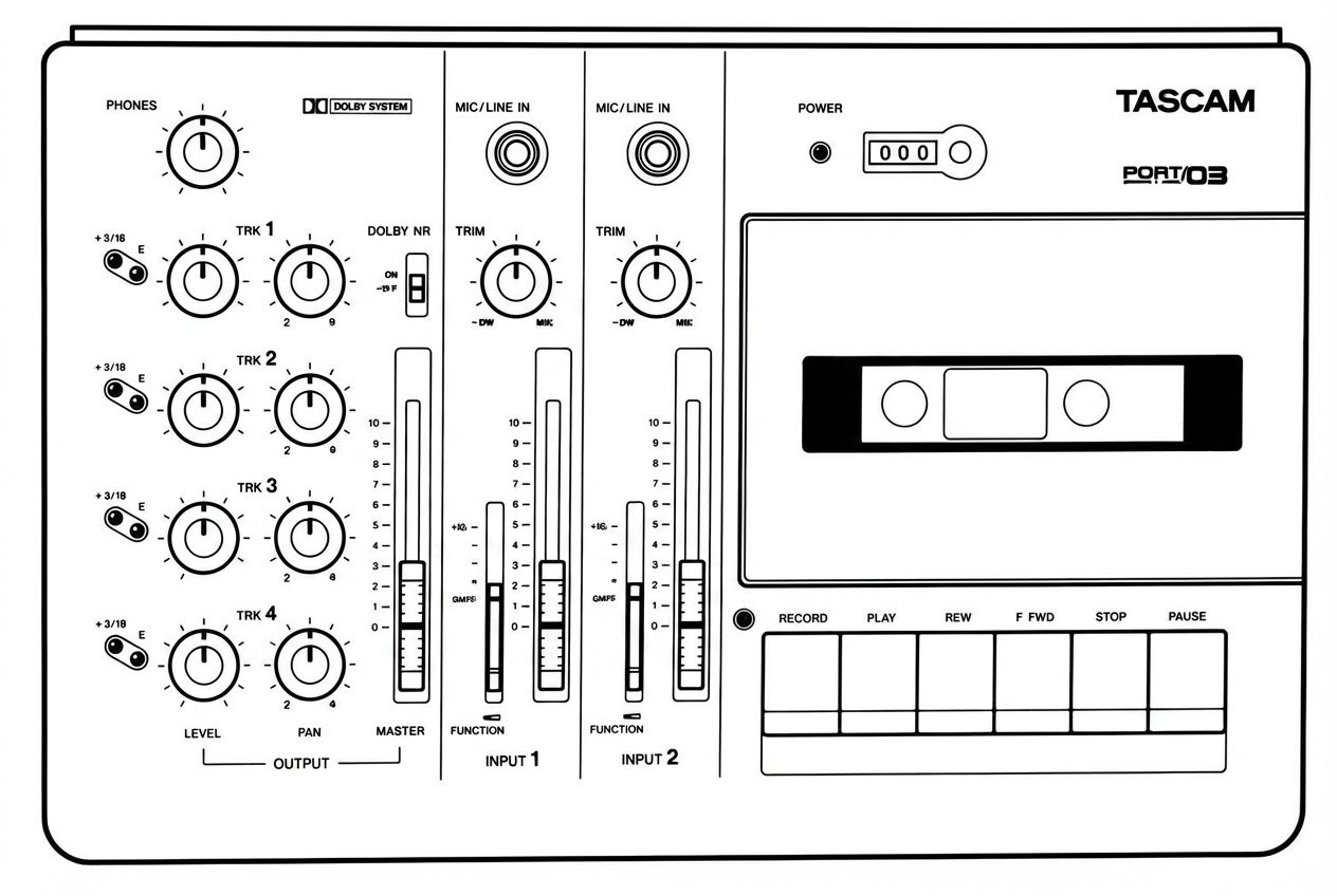
Features and Controls
Input Section
- DC IN jack — For connection to the provided PS-P2/PS-P3 AC adaptor.
- POWER switch — Turns the PORTA 03 on and off, as indicated by the POWER LED above the cassette compartment.
- MIC/LINE IN jack — This 1/4" phone jack accepts unbalanced signals ranging from -50 dBV (3 mV) to -10 dBV (0.3 V), depending on the setting of the TRIM control. Low impedance microphones may be connected to this jack. If the microphone is a balanced type with an XLR connector, simply wiring an adaptor with Pin 3 (0") and Pin 1 connected to the Sleeve (ground of the phone plug) and Pin 2 connected to the Tip (hot) of the phone plug will usually work. In some cases, a microphone unbalancing transformer may be required.
- TRIM control — This sets how much preamplification level is on the MIC/LINE Inputs. When TRIM is turned all the way to the left (LINE position), the preamplifier gain is low, allowing the jack to accept line level sources or louder sound sources. As you turn TRIM up, the preamplifier gets more gain when working with mic's or softer sound sources.
NOTE: The TRIM control has no effect on the tape playback signals.
- Input Fader — This linear (slide) fader varies the amount of signal going from the input channel to the tape via the channel's REC FUNCTION switch, and to the LINE OUT (and PHONES) jacks via the PAN control.
- REC FUNCTION switches — These select which tracks the INPUT 1 and INPUT 2 signals are sent to and which tracks will be recorded with new material when RECORD is pressed.
Output Section
- LINE OUT L and R jacks — This pair of RCA jacks are typically connected to the inputs of a 2-track stereo recorder for mixdown.
- PHONES jack — For connection to stereo headphones only. If yours have a mono plug, don't use them.
Using the 2-wire connector shorts out one of the amplifiers driving the headphones, which will cause it to burn out.
- PHONES control — This adjusts the overall level of the headphones plugged into the PHONES jack. Any change in the setting of PHONES affects the listening level of the following in the headphones: TRIM controls, Input Faders, LEVEL and PAN controls, and MASTER fader. Note, however, that the TRIM controls and Input Faders adjust the recording level; don't use them to adjust the listening level of the headphones.
- Level indicators —
- In STOP (and in RECORD PAUSE too), the level indicator of a track selected by the REC FUNCTION switches is used to visually check the input level. If the orange LED constantly flashes the level is too high; turn the TRIM to the left until the LED flashes only occasionally.
- In RECORD, the level indicator of the tracks selected by the REC FUNCTION switches is used to check the level at which they are recorded. The TRIM controls and Input Faders are effective on the level indicators.
- In PLAY (including PLAY PAUSE), the indicators are used to check the playback level of each track. The LEVEL and PAN controls and any other controls and faders have no effect on the level indicators.
NOTE: Even if an input signal is plugged in, that level is not shown by any level indicators as long as the unit is in PLAY.
- LEVEL controls — These adjust how much of each track you will hear in the headphones and the LINE OUT jacks. Each LEVEL control gets signal directly from its tape track, and sends it on to the PAN control, and then to the MASTER Fader. Note that during actual recording, each LEVEL control actually gets signal from the input channel (via the REC FUNCTION switches) instead of from tape playback. For lowest noise and best clarity, be sure to "shut off" (turn counterclockwise) the LEVEL control of any tracks that are blank, or that you don't need to hear.
- PAN — Each PAN controls the left-right position of its track in the MASTER stereo mix, both in the headphones and the L and R LINE OUT jacks.
- MASTER fader — This is the stereo master volume control for the 4x2 tape cue monitor section. It has no effect on the recording level of the tracks, which are set by the Input Fader and TRIM. At mixdown time, MASTER is used to control the overall mix level feeding the 2-track recorder connected to the LINE OUT jacks, or to adjust the level at the PHONES jack.
Recorder Section
- Cassette compartment door — Once a cassette is inserted, be sure to close the door. This will prevent foreign objects, dust or liquids from falling into the tape path.
- Tape counter with reset button — This 3-digit counter shows the distance the tape has moved from a zero reference point. Each time you press the adjacent small button a new zero reference point is established.
- DOLBY NR switch — Turns on and off the incorporated Dolby B noise reduction system. Generally the switch should be on. Only when playing a tape recorded without Dolby NR, should the switch be Off.
- RECORD key — 1) When this sole key is pressed, PLAY also automatically is, and record starts on the track or tracks selected by the REC FUNCTION switch(es). 2) If RECORD is pressed while PLAY is held down after tape has started playing, the selected track will start recording ("punch-in"). The LED above the RECORD key will light as long as record is taking place on any tracks.
- PLAY key — Starts tape to play.
- REW key — Winds tape at high speed in reverse.
- F.FWD key — Winds tape at high speed in the forward direction.
- STOP key — Stops any tape motion.
- PAUSE key — Interrupts play or record temporarily. To resume the function interrupted, press PAUSE again.
To punch out of record also use PAUSE (and not STOP). This makes the punch out cleaner.
Care and Maintenance
Even though the heads used in your PORTA 03 have high wear resistance and are rigidly constructed, performance degradation or electro-mechanical failure can be prevented if maintenance is performed regularly.
Cleaning
The first things you will need for maintenance are not expensive. The winding kit with swabs and fluids you will need for months will cost less than a couple of high quality cassettes.
We cannot stress the importance of cleaning too much. Clean up before each session. Clean up after every session. Clean up every time you take a break in the middle of a session.
Here's why:
- Any dirt or oxide build-up on the heads will force the tape away from the gaps that record and playback. This will significantly affect the response. Even so small a layer of dirt as one thousandth of an inch will result in degraded performance. All the money you have paid for high performance will be wiped out by a bit of dirt. Wipe it off with the head cleaner and you're back to normal.
- Tape and tape oxide act very much the same way as fine sandpaper. The combination will slowly grind down the tape path. If you do not clean all of this abrasive material on a regular basis, the wear will be much more rapid and will become irregular. Even wear on heads can be compensated for with electronic adjustments for awhile, but uneven wear can produce notches on heads and guides that will cause the tape to "skew" and skip around, making adjustment impossible. This ragged pathway chews up the tape, producing more abrasive material, which in turn causes more uneven wear. This begins a vicious circle that cannot be stopped once it gets a good start. The only solution to this will be to replace not only the heads, but the tape guides as well. Being conscientious about cleaning the tape path on your PORTA 03 will more than double the life of the heads and tape guides.
Cleaning the Heads and Tape Guides
All heads and metal parts in the tape path must be cleaned after every 8 hours of operation, or before starting and after ending a recording session.
- Open the cassette door.
- Using a good head cleaning fluid and a cotton swab, clean the heads and tape guides until the swab comes clean. Wipe off any excess cleaning fluid with a dry swab.
Cleaning the Pinch Roller
Clean the pinch roller at least once each day the deck is in use. Use a good rubber cleaner.
- Push up the transport protection lever as illustrated. Press the PLAY key to engage the pinch roller and capstan shaft, while holding the protection lever up.
- Lightly press a cotton swab moistened with rubber cleaner to the pinch roller on the right hand side of the capstan shaft. This will prevent the swab from becoming entangled. Clean it until there is no visible residue coming off onto a clean swab.
- Using a clean cotton swab, wipe off all the excess rubber cleaner from the pinch roller. Make certain that there is no foreign matter remaining on either the pinch roller or the capstan shaft.
Degaussing (Demagnetizing)
A little stray magnetism can become quite a big nuisance in tape recording. It only takes a small amount (2 Gauss) to cause trouble on the record head. Playing 10 cassettes will put about that much charge on the heads. A little more than that (7 Gauss) will start to erase high frequency signals on previously recorded tapes. You can see that it's worth taking the trouble to degauss regularly.
DEGAUSSING IS ALWAYS DONE WITH THE RECORDER TURNED OFF. If you try it with the electronics on, the current pulses produced by the degausser will just like audio signals to the heads. These pulses are around 10,000 Gauss and will seriously damage the electronics and/or meters. Turn off your PORTA 03, then turn on the degausser at least 1 m (3 feet) away from the recorder.
Slowly move in to the tape path. Move the degausser slowly back and forth, touching lightly all metal parts in the tape path. Slowly move it away again to at least 1 m (3 feet) from the recorder before turning it off.
Be sure to concentrate while you are degaussing. Don't try to hold a conversation or think of anything else but the job you are doing. If the degausser is turned on or off by accident while it is near the heads, you may put a permanent magnetic charge on them that no amount of careful degaussing will remove. You will have to get the heads replaced. Make sure you are wide awake for this job.
A clean and properly demagnetized tape recorder will maintain its performance without any other attention for quite a while. It won't ruin previously recorded material, nor will getting it back to original specifications be difficult.
CAUTION: If the surface of the unit gets dirty, wipe the surface with a soft cloth or use a diluted neutral cleaning fluid. Clean off thoroughly. Do not use thinner, benzine, or alcohol, as they may damage the surface of the unit.
Tape Path Components
The tape path consists of the following components (from left to right):
- Tape guides — Guide the tape past the heads
- Erase head — Erases old material during recording
- Record/Play head — Records and plays back audio
- Pinch roller — Presses tape against the capstan
- Capstan — Drives the tape at constant speed
Troubleshooting
| Trouble | Possible Cause |
|---|---|
| Transport keys not effective | Power turned off; Tape not correctly loaded |
| Playback sound poor in brightness | Dirty heads |
| No playback sound | LEVEL controls turned all the way to the left/minimum position |
| No recording | Cassette tab broken; REC FUNCTION switch at SAFE |
| Wrong tracks recorded | REC FUNCTION switch improperly set |
| Noisy recordings | Recording level set too high or too low; TRIM level set too low, Channel Fader too high; LEVEL of blank tracks not turned off; DOLBY NR not turned ON |
Optional Accessories
JC-T201 Plug Adaptor
RCA Phono to 1/4" Phone adaptor. Designed to pro standard for optimum strength and sound quality with the male and female connectors machined out of one piece of metal.
TZ-261 Cleaning Kit (Except U.S.)
Complete cleaning kit for tape heads and transport components.
TASCAM Cables
Cable, because of its inherent capacitance and resistance, is an active component in an audio system. There are vast differences in cable design and performance that have significant effect on the sound quality you'll get from your equipment. TASCAM Professional Audio Cables are the best available.
If TASCAM professional cables are not available in your area, please try to find the next best cables. It really does make a difference in system performance.
HC Head Cleaner & RC Rubber Cleaner (U.S. Only)
Head cleaner and rubber cleaner solutions for maintaining the tape path and pinch roller.
Specifications
Mechanical
| Parameter | Value |
|---|---|
| Tape | Compact cassette, Type II, Hi-Bias, C-90 or shorter |
| Track format | 4-track/4-channel, single direction record/play |
| Head configuration | 4-channel recording/playback (Permalloy) x1; 4-channel erase (ferrite) x1 |
| Tape speed | 1-7/8 ips (4.8 cm/sec.) ±1% |
| Wow and flutter | 0.08% (WRMS) |
| Fast winding time | 110 sec. (approx.) with C-60 |
| Dimensions (WxHxD) | 290 x 179 x 66 mm (11-7/16" x 7-1/16" x 2-11/16") |
| Weight | 1.7 kg (2-14/16 lbs.) |
Electrical — Mixer Section
MIC/LINE Input (1/4" phone jack x2):
| Parameter | Value |
|---|---|
| Input impedance | 50,000 ohms |
| Nominal input level | -50 dBV (3mV) to -10 dBV (0.3 V) |
| Minimum input level | -60 dBV (1 mV), TRIM at max |
| Maximum input level | -4 dBV (2.0 V), TRIM at min |
LINE OUT (RCA jack x2):
| Parameter | Value |
|---|---|
| Output impedance | 1,000 ohms |
| Nominal output level | -10 dBV (0.3 V) |
| Minimum load impedance | 2,000 ohms |
| Maximum output level | +6 dBV (2.0 V) |
PHONES output (1/4" jack x1):
| Parameter | Value |
|---|---|
| Impedance | 8 ohms |
| Maximum output level | 100 mW + 100 mW |
Typical Performance
| Parameter | Value |
|---|---|
| Overall frequency response | 40 Hz to 12.5 kHz, ±3 dB |
| Overall signal-to-noise ratio | 50 dB (IHF A-weighted) |
| Crosstalk/channel separation (THD) | 50 dB (at 1 kHz) |
| Channel separation | 50 dB (at 1 kHz) |
| Erasure | 65 dB (at 1 kHz) |
Others
| Parameter | Value |
|---|---|
| Power requirement | 11-15 V, 400 mA DC, via the provided PS-P2/PS-P3 AC-DC adaptor |
| Consumption | 4.8 W |
Changes in specifications and features can be made without prior notice or obligation.
Dolby and the double D symbol are trademarks of Dolby Laboratories Licensing Corporation. Dolby Noise Reduction system is manufactured under license from Dolby Laboratories Licensing Corporation.
Porta 03 Brief Guide
For detailed information on each feature, see Features and Controls.
Input Section
- MIC/LINE IN — These jacks accept both line level and mic level sources.
- TRIM — Sets how much amplification will be added to the MIC/LINE IN jack. Turn to the right (MIC side) for more amplification. Turn to the left when using a line level or louder sound source such as electronic instruments.
- DOLBY NR — This turns the Dolby B Noise Reduction system on and off. Normally, leave it on.
- REC FUNCTION switches — They select which tracks will be recorded. It is possible to record two tracks at once.
- Input Fader — Sets the volume of the input channel signal feeding the tape.
- DC IN — Connect the provided PS-P2/PS-P3 AC adaptor. When the DC IN is correctly connected and the POWER switch is set to ON, the POWER indicator above the cassette compartment lights.
4x2 Tape Cue Monitor/Output Section
- PHONES control — This adjusts the listening level of the headphones plugged into the PHONES jack on the left side of the PORTA 03.
- Level Indicators — In STOP, RECORD, and RECORD PAUSE, these show the input signal level assigned (sent) to the respective tracks. In PLAY and PLAY PAUSE, they show the playback level of each track.
- MASTER — This is the overall level control for the 4x2 tape cue mixer section. At mixdown time, the MASTER fader controls the playback level of the four tracks feeding your stereo deck.
- PAN — Sets the pan position (left-right balance) of each track between L/R LINE OUTPUTS as monitored to the headphones.
- LEVEL controls — These adjust how much playback signal of the individual tracks you will hear in the headphones and send to the LINE OUT jacks.
Recorder Section
- Tape counter and Reset button — A three-digit display that shows the current tape position. Press the adjacent small button to establish a new 000 reference point.
- Transport keys — To start recording from STOP, press the sole RECORD key. In PLAY, recording when tape is playing, hold PLAY and press RECORD key. The RECORD LED lights up as long as a track or tracks are being recorded. The other keys work the same as on conventional cassette recorders.
Connections
- PHONES jack — For connection to stereo headphones.
- LINE OUT L and R jacks — Connect these plugs to the left and right inputs of your stereo deck.
Block Diagram
Note: This section contains a block diagram that was present as a visual schematic in the original scanned manual. The diagram shows the signal flow through the Porta 03.
Signal Flow Summary
Input Path
MIC/LINE IN (Input 1) → TRIM → Input Fader → REC FUNCTION Switch → Track Select (TRK 1-4)
MIC/LINE IN (Input 2) → TRIM → Input Fader → REC FUNCTION Switch → Track Select (TRK 1-4)
Recording Path
Selected Input → Record/Play Head → Tape (TRK 1, TRK 2, TRK 3, TRK 4)
Playback/Monitor Path
Tape Track → LEVEL Control → PAN Control → MASTER Fader → LINE OUT L/R
                                                             → PHONES (via PHONES Control)
Erase Path
REC FUNCTION Switch → Erase Head (erases selected tracks during recording)
Dolby B NR
Applied in the record and playback paths when DOLBY NR switch is ON.
DC Power
DC IN → PS-P2/PS-P3 AC Adaptor → Power Supply → All circuits
Level Diagrams
Note: This section contains level diagrams that were present as visual schematics in the original scanned manual. The diagrams illustrate the signal levels at various points in the Porta 03's signal chain.
Signal Level Reference Points
| Point in Signal Chain | Nominal Level |
|---|---|
| MIC/LINE IN (mic position) | -50 dBV (3 mV) |
| MIC/LINE IN (line position) | -10 dBV (0.3 V) |
| Maximum input level | -4 dBV (2.0 V) |
| LINE OUT nominal | -10 dBV (0.3 V) |
| LINE OUT maximum | +6 dBV (2.0 V) |
| PHONES maximum | 100 mW + 100 mW |
Level Indicator Behavior
In STOP / RECORD PAUSE Mode
The level indicators show the input signal level assigned to the respective tracks via the REC FUNCTION switches.
In RECORD Mode
The level indicators show the recording level of the tracks selected by the REC FUNCTION switches. The TRIM controls and Input Faders affect the level indicators.
In PLAY / PLAY PAUSE Mode
The level indicators show the playback level of each track. Controls and faders have no effect on the level indicators.
Optimal Level Setting
- Green LED on — Signal present at good level
- Orange LED flashing occasionally — Ideal recording level
- Orange LED constantly on — Level too high; reduce TRIM